Introduction
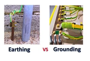
In electrical engineering, grounding and earthing are critical safety and operational concepts. Although often used interchangeably in everyday language, they have distinct purposes and technical implementations.
- Earthing protects human life by connecting exposed metal parts of equipment to the Earth.
- Grounding stabilizes electrical systems by connecting current-carrying points (like neutrals) to Earth.
Understanding these distinctions is essential for designing safe and reliable power systems, fault protection schemes, and industrial installations.
Fundamental Principles
Electrical Reference to Earth
The Earth acts as a vast reservoir of charge with essentially zero electrical potential. Connecting systems or equipment to Earth provides a reference point for voltage and a safe path for fault currents.
- Ohm’s Law and Kirchhoff’s Current Law explain how fault currents flow through low-resistance paths.
- The potential difference between system points and Earth is minimized by proper grounding and earthing.
Earthing (Protective Earthing, PE)
Definition
Earthing connects non-current-carrying metal parts of electrical equipment to Earth. Its primary goal is human safety.
How It Works
- Under normal operation, equipment bodies are at Earth potential.
- During a fault (line-to-body), current flows through the earthing conductor to Earth.
- Protective devices such as fuses or circuit breakers trip to disconnect power.
Methods of Earthing
- Plate Earthing: Copper or GI plate buried vertically in moist soil, surrounded by charcoal and salt for conductivity.
- Pipe Earthing: Perforated GI pipe driven into soil; commonly used in residential installations.
- Rod Earthing: Copper or galvanized rod driven deep into the ground; suitable for rocky areas.
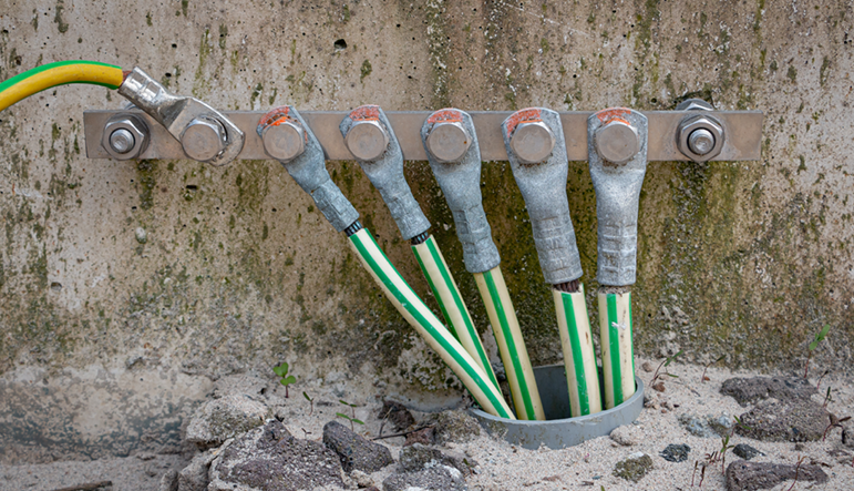
- Strip/Wire Earthing: Conductive strips buried horizontally; used in substations.
Design Considerations
- Resistance should be ≤ 5 Ω for residential and ≤ 1 Ω for substations.
- Moisture, soil resistivity, and electrode area influence earthing effectiveness.
- Periodic inspection is needed to prevent corrosion and maintain low resistance.
Grounding (System Grounding)
Definition
Grounding connects a current-carrying point (neutral of a generator, transformer, or system bus) to Earth. Its primary goal is system stability and fault protection.
Types of System Grounding
- Solid Grounding: Direct connection of neutral to Earth.
- Advantage: High fault current ensures rapid operation of protective devices.
- Disadvantage: Can cause high stress on equipment.
- Resistance Grounding: A resistor limits the fault current.
- Reduces stress on equipment.
- Common in industrial systems.
- Reactance Grounding: An inductor limits fault current.
- Used in large industrial power systems.
- Ungrounded System: No intentional connection to Earth.
- Voltage can float and cause overvoltages; less commonly used.
How Grounding Works
- Provides a reference voltage for the system.
- Enables predictable fault currents, allowing protective devices to operate.
- Reduces transient overvoltages during faults or lightning strikes.
Grounding vs Earthing: Technical Comparison
| Parameter | Earthing (Protective) | Grounding (System) |
|---|---|---|
| Purpose | Human safety | System stability & operation |
| Circuit involvement | Non-current-carrying parts | Current-carrying points (neutral) |
| Current flow | Only during faults | Continuous in normal operation possible |
| Voltage reference | Equipment body potential ≈ 0 V | Neutral/system voltage reference |
| Design focus | Safety of users | System reliability and protection |
Fault Current and Protection
Earthing Fault Example
- Phase conductor contacts a metal enclosure.
- Fault current flows to Earth through the earthing conductor.
- Overcurrent protective device trips.
- User is safe; equipment is protected.
Grounding Fault Example
- Transformer neutral grounded.
- Single line-to-ground fault occurs.
- Fault current flows through the neutral to Earth.
- Protective relays detect and isolate the fault.
Calculating Fault Current
For solidly grounded systems:If=Zsystem+ZearthVphase
Where:
- If = fault current
- Vphase = phase voltage
- Zsystem = system impedance
- Zearth = grounding/earthing resistance
Standards and Best Practices
- IEC: Defines earthing and grounding terminology, electrode requirements, and maximum resistance values.
- IEEE: Provides system grounding guidelines and protective device coordination.
Best Practices
- Separate earthing for protective and system purposes.
- Low-resistance electrodes in high-risk areas.
- Routine testing for corrosion and resistance.
- Compliance with local regulations (e.g., NEC, IEC 60364).
Practical Example: Industrial Substation
- Grounding: Transformer neutral solidly grounded to Earth for system stability.
- Earthing: All metallic enclosures of switchgear connected to Earth via earthing grid.
- Outcome: Rapid fault isolation, minimal touch voltage, system reliability maintained.
Conclusion
Proper design requires understanding soil conditions, resistance calculations, and compliance with standards.
Earthing protects people.
Grounding stabilizes systems.
Both are essential for safe and reliable electrical installations.
see: Grounding
One thought on “Grounding vs Earthing: A Technical Guide”