Introduction
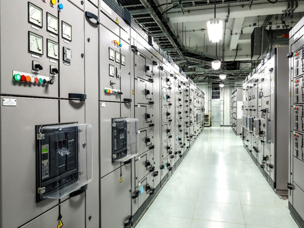
Power systems require reliable protection and control to carryout operations safely. Without proper protection, faults can cause damage to equipment and disrupt power supply. This is where switchgear becomes essential in power systems.
Understanding how Switchgear plays a critical role in isolating faults, controlling electrical circuits, and ensuring system stability. In this guide, you will learn what switchgear is, how it works, and the different types used in modern power systems. A switchgear refers to a combination of electrical devices used to control, protect, and isolate electrical equipment.
In simple terms, it allows electrical engineers to:
- Turn power systems on or off
- Protect equipment from faults
- Isolate faulty sections for maintenance
Switchgear consists of several critical components. Each component plays a specific role in ensuring protection, control, and safe operation of the power system.
Types of Switchgear
Switchgear can be classified based on voltage level and insulation type.
Based on Voltage Level
Low Voltage Switchgear (LV)
Used for systems below 1 kV. Common in residential and commercial installations.
Medium Voltage Switchgear (MV)
Used between 1 kV and 36 kV. Widely applied in industrial and distribution systems.
High Voltage Switchgear (HV)
Used above 36 kV. Found in transmission networks and large substations.
Components of a switchgear
- Circuit Breakers
Circuit breakers are the most important components in switchgear. They are responsible for interrupting fault currents and protecting the system from damage.
Under normal conditions, the circuit breaker remains closed and allows current to flow. However, when a fault occurs, the protection relay sends a signal to the breaker. As a result, the breaker opens its contacts and stops the current flow.
Modern circuit breakers use different arc-quenching methods, including:
- Air circuit breakers (ACB)
Air Circuit Breakers use air at atmospheric pressure to extinguish the arc formed when contacts open. When a fault occurs, the breaker separates its contacts. Consequently, an arc forms between them. The ACB controls and cools this arc using arc chutes and air flow until it is completely extinguished.
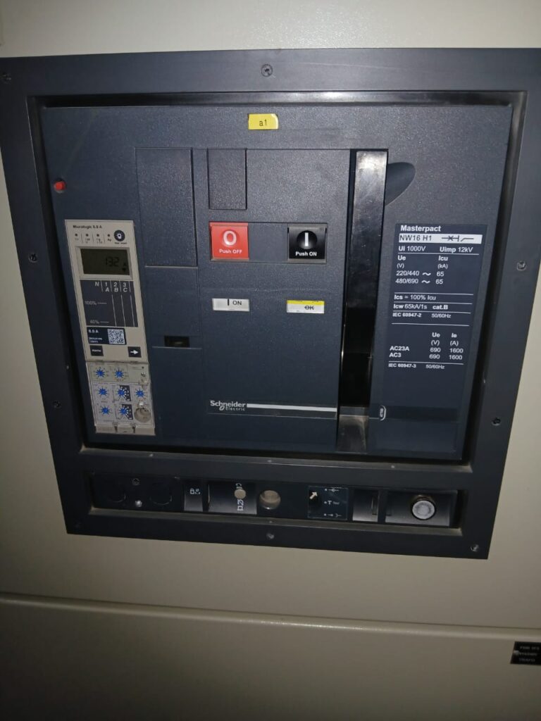
Key Features:
Operates in low voltage systems (typically up to 1 kV)
Easy maintenance and inspection
No risk of gas leakage or environmental hazards
- Vacuum Circuit Breakers (VCB)
Vacuum Circuit Breakers extinguish the arc inside a vacuum chamber. Since there is no air or gas, the arc cannot sustain itself for long.
When the contacts separate, a short arc forms due to metal vapor. However, the vacuum quickly suppresses it, and the current stops almost instantly.
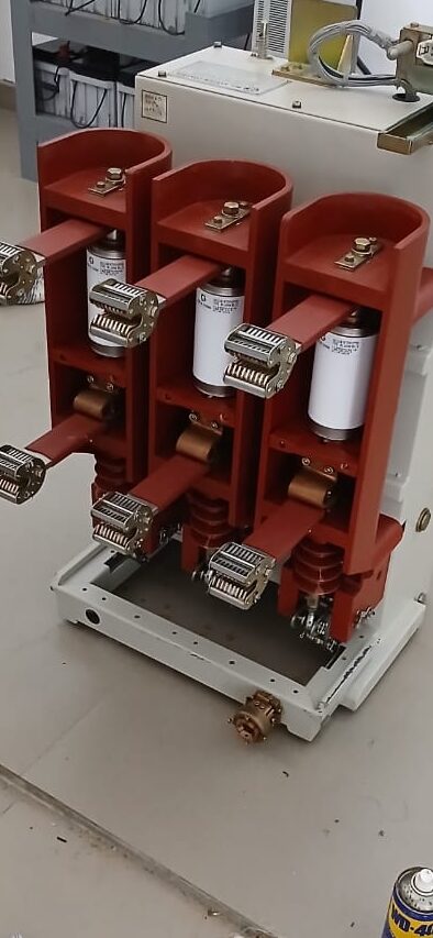
Key Features:
Very fast arc extinction
Minimal maintenance required
Long service life
High reliability
Medium voltage systems (1 kV to 36 kV)
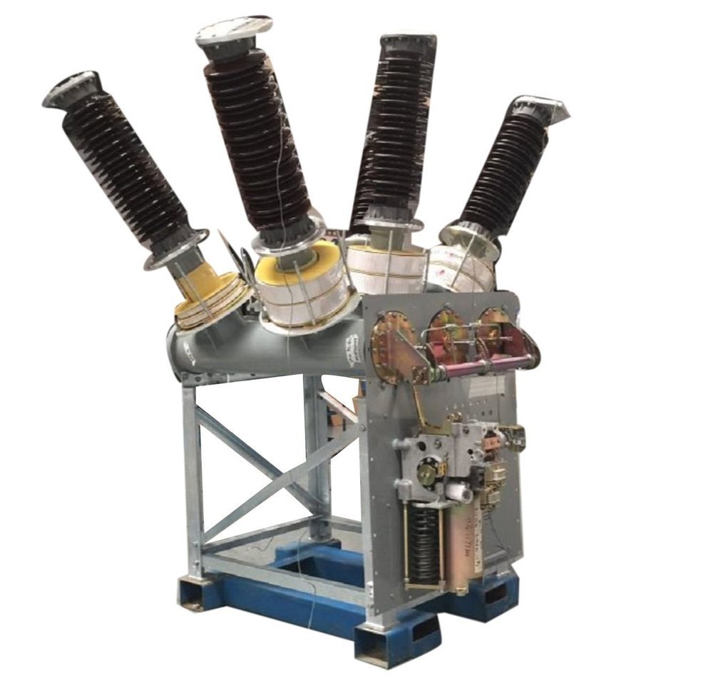
- SF₆ circuit breakers
SF₆ circuit breakers use sulfur hexafluoride gas as the arc-quenching medium. This gas has excellent insulating and arc-extinguishing properties.
When a fault occurs, the breaker releases SF₆ gas at high pressure. As a result, the gas cools and extinguishes the arc very efficiently.
Key Features:
High dielectric strength
Excellent arc quenching capability
Suitable for high voltage applications
Compact design (especially in GIS systems)
High voltage transmission systems
Each type is designed for specific voltage levels and applications. For example, vacuum circuit breakers are widely used in medium voltage systems due to their reliability and low maintenance.
- Isolators (Disconnect Switches)
Isolators are mechanical switches used to disconnect a part of the system for maintenance or safety purposes.
Unlike circuit breakers, isolators do not operate under load. Therefore, they are opened only after the circuit breaker has already interrupted the current.
Their main purpose is to provide visible isolation. This ensures that engineers can safely work on equipment without the risk of accidental energization.
In practice, isolators are often installed on both sides of circuit breakers to completely isolate faulty sections.
- Protective Relays
Protective relays act as the “brain” of the switchgear system. They continuously monitor electrical parameters such as current, voltage, frequency, and impedance.
When abnormal conditions occur, the relay detects the fault and sends a trip signal to the circuit breaker.
There are different types of relays used in switchgear, including:
- Overcurrent relays
- Distance relays
- Differential relays
- Earth fault relays
Modern systems use digital or numerical relays. These relays offer high accuracy, fast response, and advanced features such as fault recording and communication with SCADA systems.
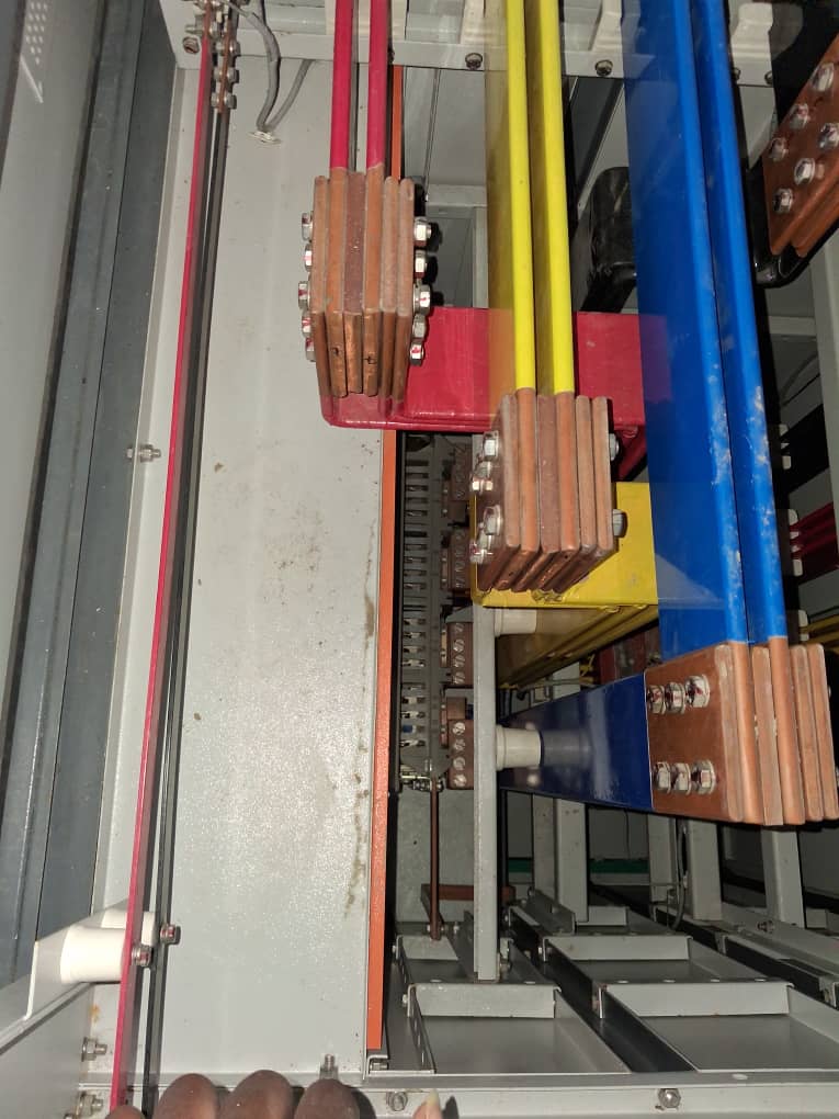
- Busbars
Busbars are metallic conductors that distribute electrical power within the switchgear assembly.
They serve as a common connection point for incoming and outgoing circuits. Because they carry large currents, busbars are made of copper or aluminum with high conductivity.
Proper busbar design is critical. It must handle:
- Thermal stress due to current flow
- Mechanical stress during faults
- Short-circuit forces
In addition, busbars are often arranged in configurations such as single bus, double bus, or ring bus systems, depending on reliability requirements.
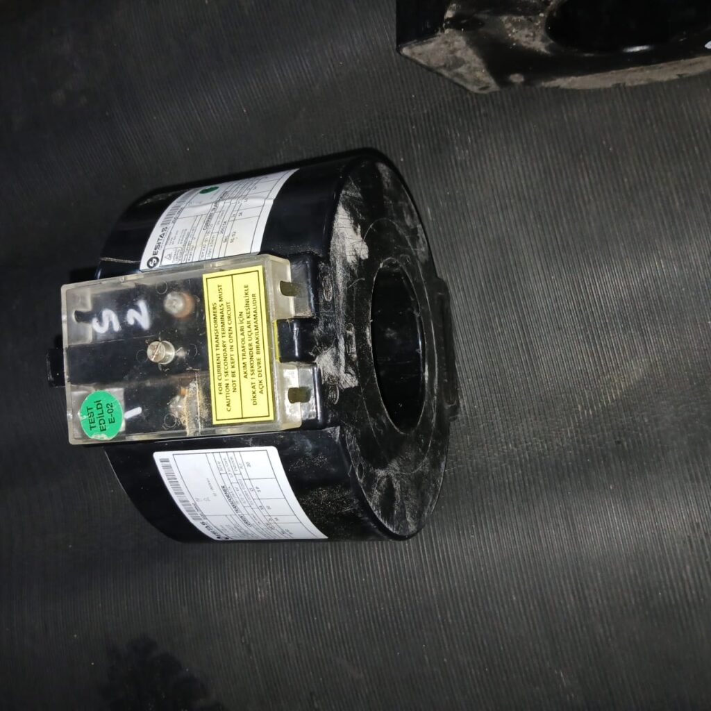
- Instrument Transformers (CTs and PTs)
Instrument transformers are used to step down high currents and voltages to safe levels for measurement and protection.
- Current Transformers (CTs) reduce high current values to standard levels (e.g., 5A or 1A)
- Potential Transformers (PTs) reduce high voltage to measurable levels
These devices allow relays and meters to operate accurately without being exposed to dangerous electrical levels.
Accuracy and proper selection of CTs and PTs are essential. Errors in these devices can lead to incorrect relay operation.
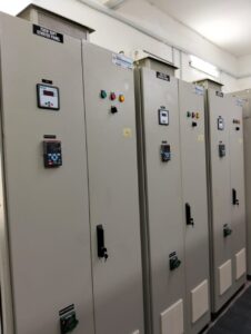
- Protection and Control Panels
These panels house the control and protection equipment of the switchgear system.
They include:
- Relay modules
- Control switches
- Indication lights
- Communication interfaces
Operators use these panels to monitor system status, control equipment, and respond to faults.
Modern panels often integrate with SCADA systems. This allows remote monitoring and control of the power system in real time.
- Earthing System
The earthing system provides a safe path for fault currents to flow into the ground.
This is essentially for:
- Protecting the equipment connected to it
- Preventing electric shock
- Ensuring proper relay operation
A well-designed earthing system reduces touch and step voltages, thereby improving overall power systems safety.
- Surge Arresters (Lightning Protection)
Surge arresters protect switchgear from voltage spikes caused by lightning or switching operations.
When a surge occurs, the arrester diverts excess voltage to the ground. As a result, it prevents insulation damage and equipment failure.
They are especially important in outdoor substations and high-voltage installations.