When working with a PoE NVR system – a video recorder with a built-in PoE switch (power-sourcing equipment, PSE) with one LAN port and is not to be operated as a standalone but linked to a corporate network via the LAN port while only the NVR is to be available on the corporate network, one will face one of these challenges:
- The connection of extra cameras to the NVR when the number of cameras exceeds the number of PoE ports: in cases where the number of channels supported by the NVR is more than the number of PoE ports.
- Connecting a camera or network of cameras located beyond 100m to the NVR PoE port: this will be a result of maintaining the maximum distance of 100m between IP devices as recommended in the IEEE802 standard that has to do with managing voltage drop along the transmission line and communication efficiency in terms of speed.
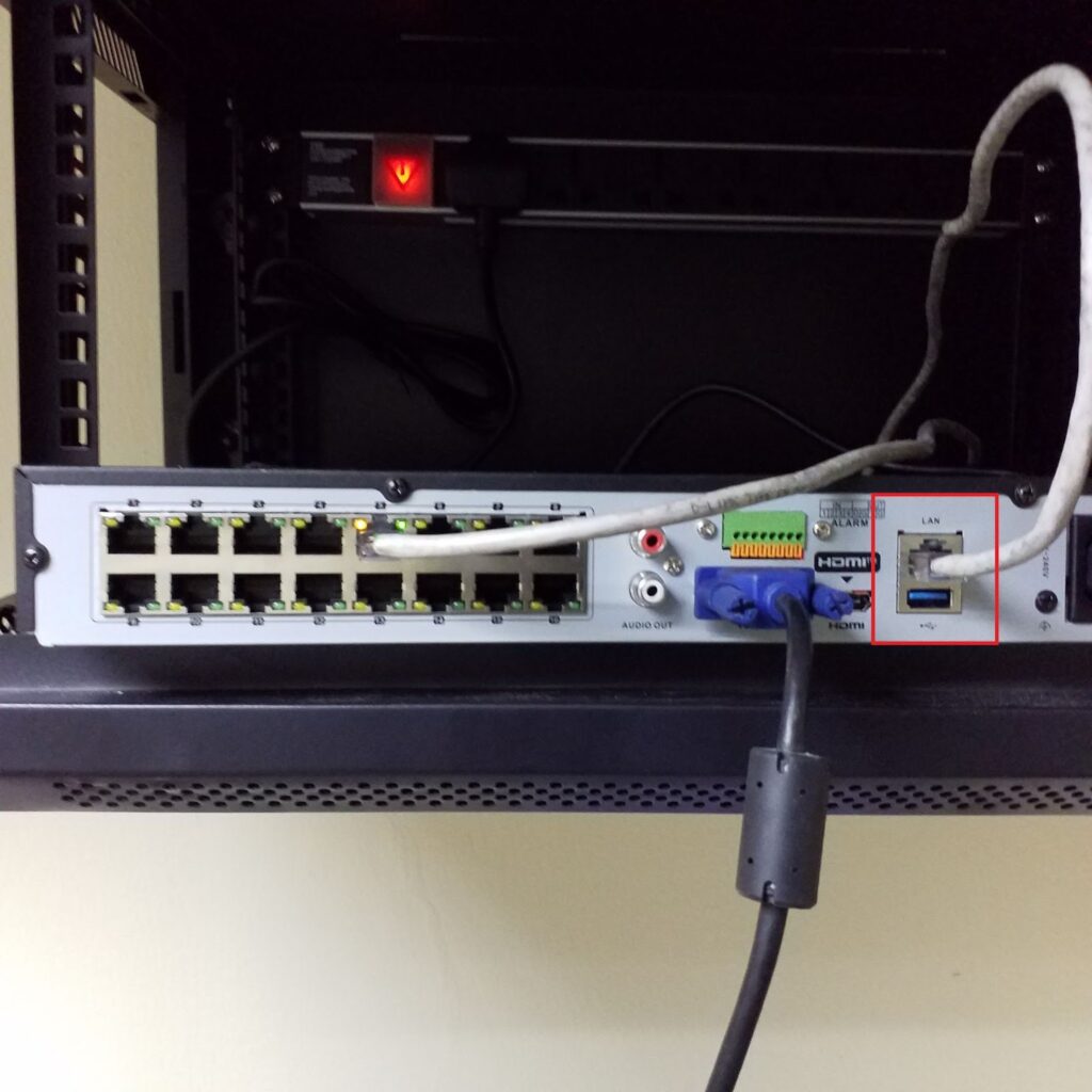
Whether you come across the first problem or the second issue as I did, solving it will require basic but important knowledge about the NVR LAN and PoE ports. The LAN port is a Gigabit Ethernet port, while the PoE ports are Megabit – Mbps Ethernet ports. So, when extending any of the PoE ports, you must ensure the connected cameras’ effective bandwidth (with the desired decoding/compression setting). It must be within the rated bandwidth of the PoE ports of the NVR you are working with. The LAN port has an IP address for the external connection with the NVR (IPv4 or IPv6). However, the NVR has an internal IP address for connecting with devices connected to its PoE ports. All devices connected to the NVR through the PoE ports must be in the same subnet mask with the internal IP address.
There are two ways to solve any of the two problems listed above:
- The first solution is to use a PoE switch and a CAT 6 ethernet cable: with the PoE switch, form a network of cameras by connecting all the cameras to it. Next, access the PoE setting of the NVR and disable PoE binding on the PoE port(s) you intend to connect the network to. The total number of PoE binding to be disabled must correspond with the number of additional cameras. If there are 3 cameras connected to the PoE switch, then 3 ports including the port to which the small network is to be physically connected to has to be disabled on PoE binding. Then, connect the PoE switch via its uplink port to the PoE port of the NVR with a CAT 6 cable. In order not to have a connection with a higher bandwidth than the PoE port, connect a smaller network of cameras made with PoE switches to different PoE ports. Once successful with your setup, you can search and add your cameras to your NVR.
- The second solution is to use a fibre-linked network: this is similar to the first solution but also different. It is applicable and useful when the distance between the cameras and the NVR is beyond 100m. In this case, you must connect the cameras through a PoE switch to a fibre media converter—a PoE-enabled media converter can also be used. The connection is then linked to another media converter via an optic fibre connection at the NVR’s end. The end media converter is then connected to the NVR’s PoE port with a CAT 6 cable, having disabled the required PoE ports on PoE binding. To disable PoE binding, access the PoE setting of the NVR and disable PoE binding on the PoE port(s) you intend to connect the network to. The total number of PoE bindings to be disabled must correspond with the number of additional cameras. If there are 5 cameras connected to the PoE switch, then 5 ports, including the port to which the small network will be physically connected, should be disabled on PoE binding. The last thing to do is search the list of online devices and add your cameras to your NVR.
Step-by-step procedures that were taken to implement the solution:
Step 1:
I connected my installed cameras – nine (9) cameras, through PoE switches and linked each camera to a fibre network with a media converter. The uplink of my fibre network was connected to a media converter placed within a room where the NVR was installed. I connected a CAT 6 patch cord to the media converter. My cameras were assigned IP addresses with the same subnet and subnet mask.
So, ensure you have successfully powered your cameras with PSE and interconnect them to form a network. Configure your cameras with IP addresses with the same subnet and subnet mask.
Step 2:
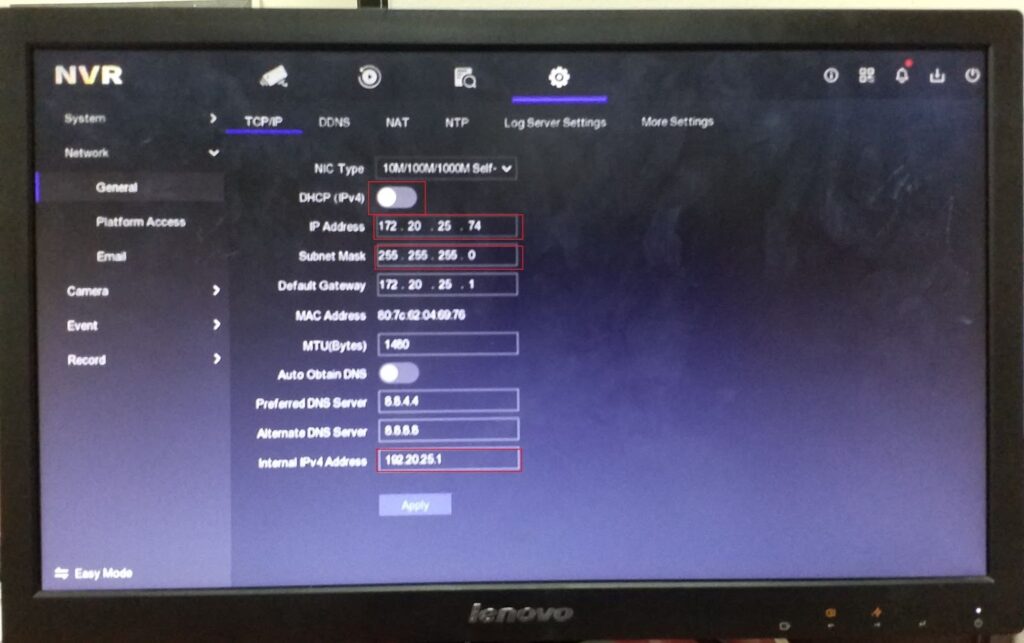
I accessed the Network>General > TCP/IP setting of my NVR and disabled IPv4 DHCP. The IPv4 address which is the IP for the NVR LAN was assigned an address within the subnet of the corporate network. The internal IPv4 address was assigned within the subnet used by the cameras. I ensured the correct subnet mask in both cases. Next, I clicked apply.
Access your NVR and assign the correct IP address in the correct subnet and Subnet mask.
Step 3:
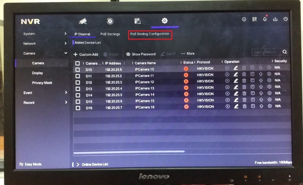
I accessed Camera > PoE Binding Configuration and disabled PoE binding on 9 channels. PoE binding ties a PoE port number to a corresponding channel number; making it compulsory that the connected camera has an IP address corresponding to the internal IP address corresponding (automatically assigned by the NVR) to that port for it to play. Once successfully unbound, the number of IP channels is reduced to only the number left bounded – 7.
Go to Camera > PoE Binding Configuration and disable PoE binding on channels corresponding to the number of cameras to be added.
Step 4:
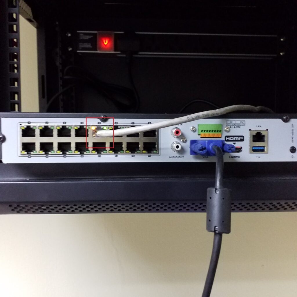
I connected the end of the CAT 6 patch cord from my media converter to one of the unbounded PoE ports.
Connect your ethernet patch cord to any unbound PoE ports on your NVR.
Step 5:
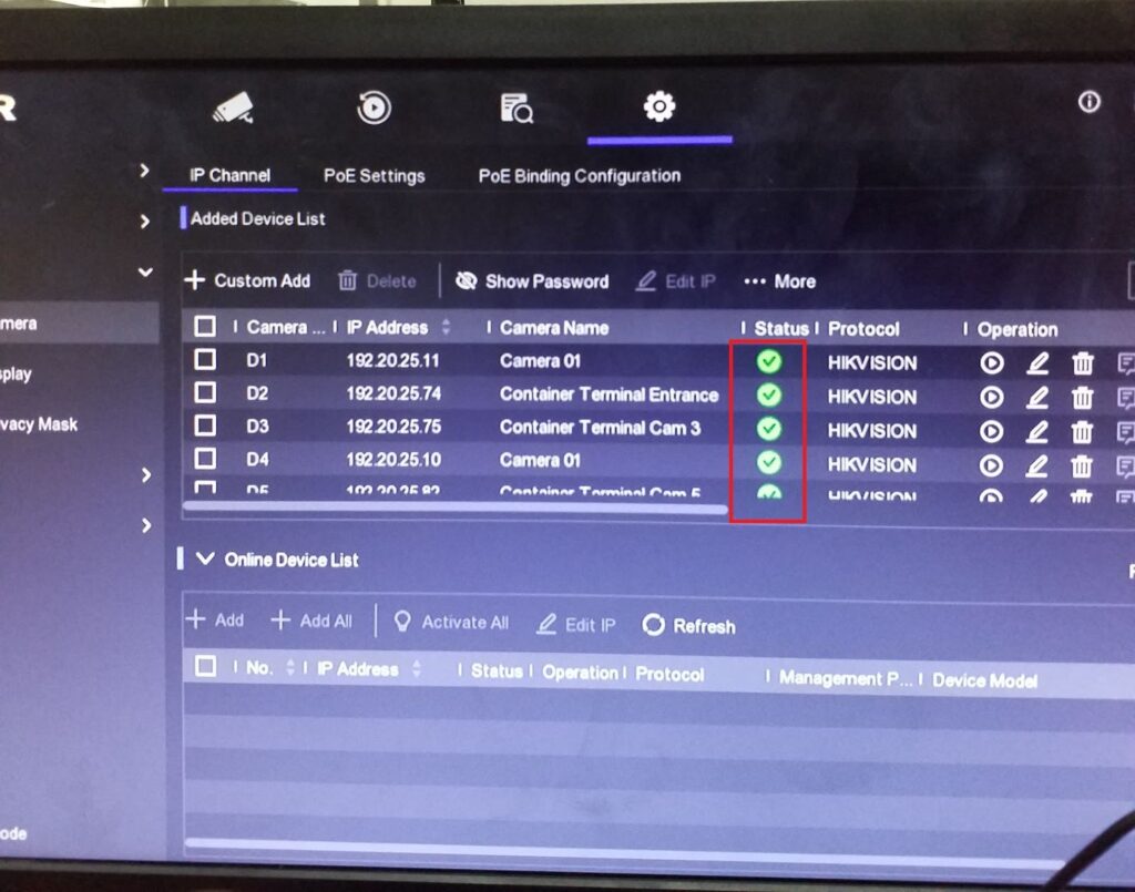
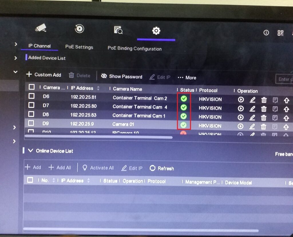
I viewed the number of devices brought online successfully.
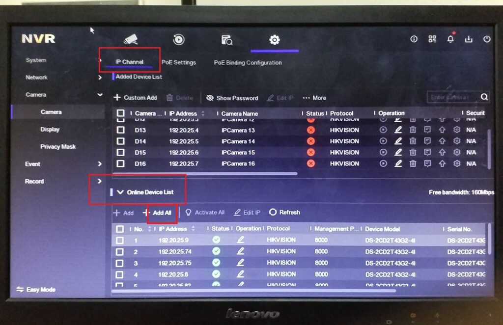
Go to IP channel under Camera parameters and view the list of cameras available online.

Step 6:
I selected Add all to add the available cameras to my NVR.
Select individual cameras and select “Add” to add the camera or select “Add All” to add the available devices to your NVR.
Step 7:
I connected my NVR to the corporate network via the NVR’s LAN port and could view my NVR from anywhere (node/terminal) on the network.
Hook up your NVR to your corporate network via your NVR LAN and perform further configurations, settings, and management according to your security demands or your organisation’s or client’s requirements.